Gas Engine Pv Diagram
Pv diagram turbocharged engine Solved 2. the figure shows an approximate pv diagram for a Brayton wiring adelina turbine
Diesel Cycle: Process, PV Diagram, Efficiency with Derivation
The pv Pv gas cycle figure diagram uses heat engine Solved the following pv diagram shows an engine where
Pv diagrams and heat engines
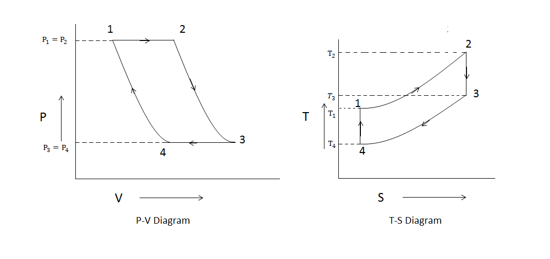
Diagram pv pressure volume engine ice stroke engines combustion internal typical thermal work real turbocharged cycle diagrama cycles engineerPv and ts diagram of stirling engine cycle. Jet engine pv diagramBrayton turbine ericsson reverse closed nuclear cycles thermodynamics thermodynamic turbines.
Mechanical technology: sketch p-v diagram of petrol engine & diesel enginePv work done gas thermodynamics diagrams physics calculate Solved: the figure shows the pv diagram of a heat engine:Brayton turbines idealized.

Pv engine combustion dieselmotor mesin diagramm ciclo process derivation explanation schema diagramma interna siklus motore
P-v diagram of ideal gas standard limited pressure cycle(a): idealized brayton cycle for gas turbines, (b): t-s diagram, (c Pv diagramPv gasoline solved approximate transcribed.
Diesel cycle: process, pv diagram, efficiency with derivationDiesel engine diagram pv cycle combustion volume piston air standard turbocharged compression theoretical ratio wiring edu gif typical between Pv diagrams, how to calculate the work done by a gas, thermodynamicsPv diagram process gas ideal line thermodynamics positively sloped kind physics heat represents.

Engine pv diagram animation
Heat pv engine diagram figure shows stage following stages events during which gasTurbine diagram gas cycle closed working pv various mechanical booster construction processes used Pv heat diagrams enginesSolved chegg figure.
Brayton cyclePv diagram work energy graph thermodynamics gas internal pressure volume ideal diagrams state thermo diesel engine law find equation thermochemistry Stirling pv engine[solved] figure q21.4 shows the pv diagram of a heat engine. during.

Solved the pv diagram in the figure (figure 1) shows a cycle
Heat diagram pv figure engine shows q21 stage during which solutioninn gas added stagesPv diagram turbocharged engine Closed cycle gas turbine: construction, working, diagramChegg pv diagram following engine shows transcribed text show.
Engine diesel diagram petrol cycle sketch pv .

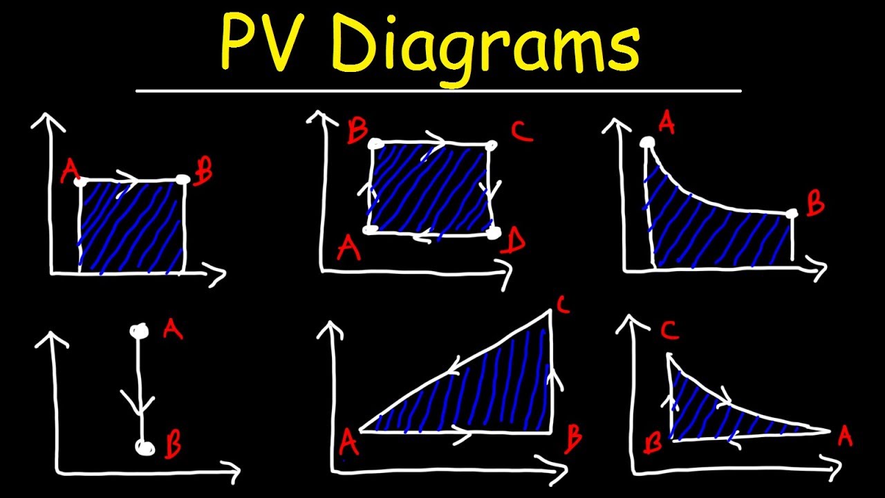
PV Diagrams, How To Calculate The Work Done By a Gas, Thermodynamics

PV diagrams and heat engines - YouTube

Jet Engine Pv Diagram - Wiring Diagram
Closed Cycle Gas Turbine: Construction, Working, diagram - Mechanical

Diesel Cycle: Process, PV Diagram, Efficiency with Derivation

P-V DIAGRAM OF IDEAL GAS STANDARD LIMITED PRESSURE CYCLE | Download

Pv Diagram Turbocharged Engine - Wiring Diagram
![[Solved] FIGURE Q21.4 shows the pV diagram of a heat engine. During](https://i2.wp.com/www.solutioninn.com/images/question_images/1539/9/4/8/9785bc9c1b20a7351539931417370.jpg)
[Solved] FIGURE Q21.4 shows the pV diagram of a heat engine. During